|
|
|
Note: The following page contains documentation and support software for uM-FPU V1.0, the original version of the uM-FPU floating point coprocessor.
See uM-FPU V2 or uM-FPU V3 for details on newer versions.
|
|
|
uM-FPU V1 |
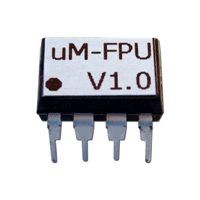
 The uM-FPU V1.0 floating point coprocessor is easily interfaced with most microcontrollers to provide support for 32-bit IEEE 754 compatible floating point and long integer operations.
The microcontroller communicates with the uM-FPU using a 2-wire or 3-wire SPI compatible interface.
The 8-pin uM-FPU uses an internal oscillator and requires no external components.
|
|
Documentation |
|
uM-FPU V1.0 Datasheet
|
248 KB |
PDF |
Oct 30, 2004 |
|
uM-FPU V1.0 Instruction Timing |
116 KB |
PDF |
Sep 8, 2004 |
|
uM-FPU V1.0 BASIC Reference |
260 KB |
PDF |
Apr 29, 2004 |
|
uM-FPU V1.0 Javelin Reference |
192 KB |
PDF |
Apr 27, 2004 |
|
uM-FPU PICAXE V1.0 Reference |
188 KB |
PDF |
Jul 7, 2004 |
|
uM-FPU V1.0 PICmicro Reference |
200 KB |
PDF |
Oct 18, 2004 |
|
uM-FPU V1.0 IDE Reference |
252 KB |
PDF |
Aug 11, 2004 |
|
Software |
|
|
BASIC Stamp Software for uM-FPU V1.0 |
20 KB |
ZIP |
May 22, 2004 |
|
Javelin Stamp Software for uM-FPU V1.0 |
24 KB |
ZIP |
May 22, 2004 |
|
PICmicro Software for uM-FPU V1.0 |
105 KB |
ZIP |
Oct 18, 2004 |
|
PICAXE Software for uM-FPU V1.0 |
12 KB |
ZIP |
May 22, 2004 |
|
PicBasic Pro Software for uM-FPU V1.0 |
16 KB |
ZIP |
Jan 21, 2005 |
|
uM-FPU V1.0 IDE (beta) |
1 MB |
ZIP |
May 22, 2004 |
|
uM-FPU Converter (with uM-FPU V1.0 samples) |
712 KB |
ZIP |
May 22, 2004 |
|
Pin Descriptions |
|
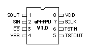
DIP-8  |
| Pin |
Name |
Type |
Description |
| 1 |
SOUT |
Output |
SPI Output |
| 2 | SIN |
Input |
SPI Input |
| 3 |
/CS |
Input |
Chip Select |
| 4 |
VSS |
Power |
Ground |
| 5 |
TSTOUT |
Output |
Test Output |
| 6 |
TSTIN |
Input |
Test Input |
| 7 |
SCLK |
Input |
SPI Clock |
| 8 |
VDD |
Power |
Supply Voltage |
|
|
|
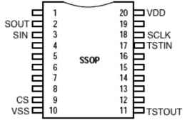
uM-FPU V1 SSOP-20
 |
|
|
uM-FPU V1 - Known Problems |
When the FTOA instruction is used for formatted output, the minus sign is sometimes not displayed properly.
|
|
This problem only occurs with formatted floating point conversions, unformatted conversions (format = 0) are not affected.
When the FTOA instruction is used for formatted output, an internal variable is set incorrectly. If the value being converted is negative, the sign is displayed properly, but if the value is positive, an internal sign variable is not set and the value will depend on the last operation that set this variable. The following workaround will fix the problem for the BASIC Stamp.
At the beginning of the Print_FloatFormat routine insert the following code:
Print_FloatFormat:
fLow.HIGHNIB = fA
fA = 0
GOSUB Fabs
GOSUB Fabs
fA = fLow.HIGHNIB
The two FABS instructions ensure that the internal variable is cleared before the FTOA instruction.
A similar workaround can be used for other microcontrollers.
|
|
|


